
x64 Paging Mechanism
Preface
During the process of learning HEVD (HackSys Extreme Vulnerable Driver), I found there were many concepts I didn’t fully understand, which prompted this article. The content is translated from reference^[1]^, with minor adjustments to the content and structure for learning purposes.
Basic Definitions
First, let us clarify the reason for the existence of paging: it is to implement virtual addresses, making the translation between virtual and physical addresses more convenient.
Theoretically, a 64-bit machine can support up to 2^64^ bytes of memory. However, for the sake of address translation efficiency, not all 64 bits are usable. In practice, bits 48 to 63 must be identical to bit 47, which divides the address space of a 64-bit machine into two valid regions:
- 0 ~ 0x7FFF FFFFFFFF
- 0x8000 00000000 ~ 0xFFFFFFFF FFFFFFFF
This mechanism is adopted to maintain consistency with 32-bit machines and simplify address translation. In 32-bit machines, the address space is split into two equal halves, with the higher address range reserved for system code and data, which helps distinguish application code from system code. Since bits 48–63 are identical to bit 47, there is no need to consider these bits during address translation. Furthermore, if CPU capabilities increase in the future, more bits can be easily utilized without changing the current configuration.
If bits 47 to 63 of a virtual address are all 1s or all 0s, we refer to this address as a canonical address. Therefore, all addresses in x64 code must be canonical addresses; using a non-canonical address triggers a page fault exception.
Address Translation
Process
The CPU translates addresses using a sequence of tables stored in memory. The entire flow is as follows:
- The CR3 register stores the physical address of the first-level table, called the Page Map Level 4 (PML4). This table is 4KB in size and contains 8-byte entries called PML4Es. Other tables introduced below share the same size and structure;
- Bits 39 to 47 of the virtual address are used to index into the PML4, locating a PML4E;
- The PML4E stores the physical address of the next-level table, called the Page Directory Pointer Table (PDPT);
- Bits 30 to 38 of the virtual address are used to index into the PDPT, locating a PDPTE;
- The PDPTE stores the physical address of the next-level table, called the Page Directory (PD);
- Bits 21 to 29 of the virtual address are used to index into the PD, locating a PDE;
- The PDE stores the physical address of the next-level table, called the Page Table (PT);
- Bits 12 to 20 of the virtual address are used to index into the PT, locating a PTE;
- The PTE stores the base address used to calculate the final physical address;
- Bits 0 to 11 of the virtual address represent the offset, which is added to the base address from the previous step to produce the final physical address.
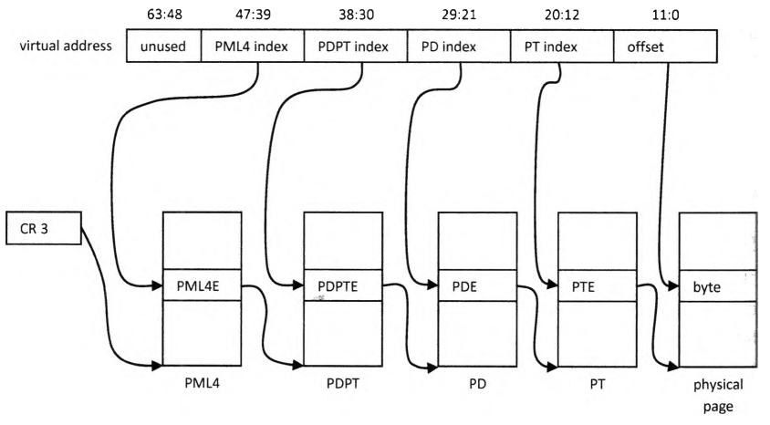
Key Concepts
Hereinafter, “paging structures” (PS) refers to the various tables described above, and “PxE” refers to the entries within these tables.
Since each paging structure is 4KB in size and each entry is 8 bytes, each paging structure contains 512 entries, which requires 9 bits of the virtual address to index.
By design, the base address of a paging structure must be aligned to a 4KB boundary. Consequently, bits 0 to 11 of such addresses are always 0, allowing the system to use these 12 bits to store control information related to address translation. The physical base address stored in a PTE follows the same alignment mechanism.
If bits 12 to 63 of different virtual addresses are identical, then based on the translation rules above, the system will resolve them to the same 4KB-aligned physical base address. Since the final offset is 12 bits, the address range covered is 2^12^ bytes, or 4KB. This 4KB-aligned physical address space of 4KB size is called a physical page. The physical page’s starting address divided by 4KB (4096) is known as the Page Frame Number (PFN).
Similarly, dividing a virtual address by 4KB (shifting right by 12 bits) yields the virtual page number, which contains all the information needed to resolve to the PFN. The block of virtual address space that shares the same virtual page number is also 4KB-aligned and 4KB in size, and is called a virtual page. All virtual addresses within the same virtual page translate to physical addresses within the same physical page, meaning the virtual page maps to that physical page.
Address Spaces of Different Processes
As observed from the address translation process, if the PML4 physical address obtained from the CR3 register differs, the same virtual address will map to entirely different physical addresses. This is how the operating system implements distinct, isolated address spaces for each process.
PxE Structure
As mentioned earlier, each PxE is 8 bytes in size, and bits 0 to 11 store control information related to address translation. Its detailed structure is shown below:
| |   62:52   |          51:12          |          11:0         |
+-+-+-+-+-+-+-+-+-+-+-+-+-+-+-+-+-+-+-+-+-+-+-+-+-+-+-+-+-+-+-+-+
|X|           |                         | | | | |P| | |P|P|U|R| |
|D|     i     |           PFN           |i|i|i|G|A|D|A|C|W|/|/|P|
| |           |                         | | | | |T| | |D|T|S|W| |
+-+-+-+-+-+-+-+-+-+-+-+-+-+-+-+-+-+-+-+-+-+-+-+-+-+-+-+-+-+-+-+-+
- P (bit 0): Present
1: Indicates the PxE is valid and points to the physical address of the next-level paging structure or the mapped physical page;0: Indicates the PxE is invalid, meaning the address space within this range is not mapped to any physical address. In this case, the remaining 63 bits are free to be used by software;
- R/W (bit 1): Read/Write
1: Indicates the mapped address range is writeable;0indicates read-only;- The WP (Write Protect) bit (bit 16) in the CR0 register has a similar function: when WP is set to 1, privileged processes (kernel mode) cannot write to read-only pages (i.e., the R/W bit of PxE is enforced). When WP is 0, privileged processes can write to read-only pages even if their R/W bit is 0.
- U/S (bit 2): User/Supervisor
1: Indicates the mapped address space can be accessed at CPL 3 (User mode);0: Indicates the mapped address space can only be accessed at CPL 0-2 (Supervisor mode/Kernel mode);
- PWT (bit 3): Page-level Write-Through, controls memory caching behavior;
- PCD (bit 4): Page-level Cache Disable, controls memory caching behavior;
- A (bit 5): Accessed, indicates whether the mapped address range has been accessed by an instruction;
- D (bit 6): Dirty
- Indicates whether the mapped address space has been written to by an instruction;
- This flag is only used in the lowest-level structures of the paging hierarchy, namely PTEs and PDEs with the PAT flag set to 1;
- PAT (bit 7): Page Attribute Table
- Reserved as 0 in PML4Es;
- Can be set to 1 in PDPTEs, but Windows does not utilize this feature;
- Can be set to 1 in PDEs, but it alters the address translation mechanism;
- In PTEs, it controls the memory caching behavior;
- The standard address translation process discussed above assumes this bit is 0 in both PDPTEs and PDEs;
- G (bit 8): Global
- Controls how the entry is cached in the Translation Lookaside Buffer (TLB);
- This flag is only used in the lowest-level structures of the paging hierarchy (PTEs and PDEs with the PAT flag set to 1);
- i: Ignored by the processor, available for system software / applications;
- PFN (bits 12 to 51): Page Frame Number, stores the PFN of the physical address pointed to by this entry;
- XD (bit 63): Execute-Disable
1: Indicates execution of code in the mapped address range is disabled;0: Indicates execution is permitted;
Address Range Mapped by PxE
The previous section mentioned the address ranges mapped by different PxEs. Let us explain this in more detail.
Just as a PTE points to the base physical address, a single fixed PTE covers an address range of 2^12^ bytes (4KB). By extension:
- A PML4E maps an address range of 2^39^ bytes (512GB);
- A PDPTE maps an address range of 2^30^ bytes (1GB);
- A PDE maps an address range of 2^21^ bytes (2MB);
The PAT Flag in a PDE
As noted in the PxE structure section, setting the PAT flag in a PDE modifies how the address translation is performed. We elaborate on this below.
If the PAT bit in a PDE is set to 1, the physical address stored in the PDE directly represents the base address of the mapped physical page, and bits 0 to 20 of the virtual address act as the offset. This translation method yields a large page of 2MB size.
By design, the physical address stored in a PDE under this configuration is 2MB-aligned, meaning its bits 0 to 20 are used entirely to store control information. The structure is as follows:
| |   62:52   |     51:21     | 20:13 | |          11:0         |
+-+-+-+-+-+-+-+-+-+-+-+-+-+-+-+-+-+-+-+-+-+-+-+-+-+-+-+-+-+-+-+-+
|X|           |               |       |P| | | | | | | |P|P|U|R| |
|D|     i     |      PFN      |  res  |A|i|i|i|G|1|D|A|C|W|/|/|P|
| |           |               |       |T| | | | | | | |D|T|S|W| |
+-+-+-+-+-+-+-+-+-+-+-+-+-+-+-+-+-+-+-+-+-+-+-+-+-+-+-+-+-+-+-+-+
- PAT: Page Attribute Table
- Normally, the PAT flag resides at bit 7. However, for a large page, bit 7 of the PDE is fixed to 1 (indicating a large page). Therefore, the PAT flag is moved to bit 12;
- Controls memory caching behavior. Note that this has the same semantics as the PAT flag in a PTE, because PAT is only relevant to the lowest-level structure in the paging hierarchy (i.e., a PTE, or a PDE in the case of a large page). Since bit 7 of the PDE is used to designate a large page, bit 12 is designated as the PAT flag instead.
Caching Mechanisms
According to the translation process described above, translating a virtual address to a physical address requires the CPU to make four memory accesses. Since memory accesses take significantly longer than instruction execution, two caching mechanisms are utilized to enhance performance: the Translation Lookaside Buffer (TLB) and Paging Structure Caches.
The TLB stores complete mapping information from virtual to physical addresses, including control bits. Thus, if a virtual address translation is found in the TLB (a TLB hit), the system bypasses memory accesses to the paging structures entirely.
Paging structure caches store partial translation steps: the PML4E cache stores information for locating the PDPT PFN, the PDPTE cache stores information for locating the PD PFN, and the PDE cache stores information for locating the PT PFN.
If software modifies a PxE structure in memory, cached entries are not automatically updated, necessitating manual cache invalidation.
When the contents of the CR3 register are changed, the system automatically invalidates the TLB. The Global (G) flag in PTEs and large-page PDEs alters this behavior. Since certain memory regions are shared across all address spaces, their translation caches do not need to be invalidated. Setting the G flag ensures that the corresponding TLB entries are preserved across CR3 reloads.
References
- What Makes It Page?: The Windows 7 (x64) Virtual Memory Manager